

Why Wind Turbine Yaw Bearing Selection Starts with Support Type?

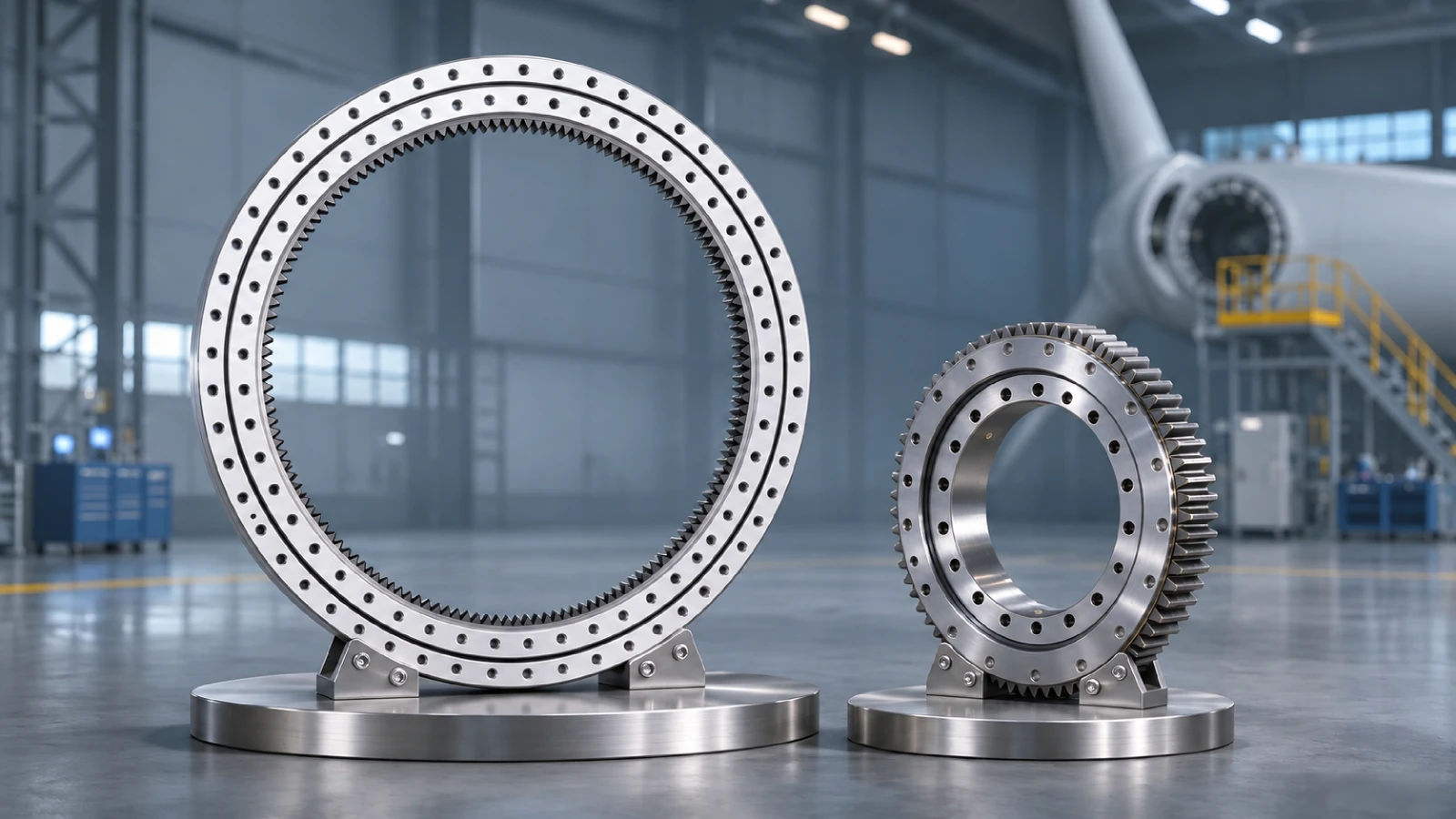
The yaw bearing on a wind turbine is the tower-top support that lets the nacelle turn toward the wind. First identify its construction: some turbines use a rolling slewing ring; others use sliding pads and liners with a separate yaw gear. Drives, brakes, bolts and flanges affect both designs, but the bearing components and inspection criteria differ. A quoted ring cannot replace an installed sliding-pad system.
For an outage purchase, use the turbine assembly drawing to define the actual support and the parts to be renewed. Check the gear and brake interfaces, mounting faces and approval date before comparing supply options. The term wind turbine yaw bearing describes a position, not one universal ring design.
How Do Rolling and Sliding Yaw Supports Carry Load?
A rolling yaw slewing ring connects the tower-top flange to the nacelle through raceways and balls or rollers. It carries nacelle weight, radial reaction and overturning moment through the rolling contacts and bolted rings. A sliding yaw design carries those loads through distributed pads or liners against a mating track. Pad retention, contact pressure, wear limits and friction then become central specifications.
Pitch bearings sit at blade-to-hub joints; main-shaft and gearbox bearings support rotating shafts. For yaw, identify the tower-top assembly and whether the support uses rolling elements or pads. Similar nacelle and tower diameters cannot make the two architectures interchangeable.
The drawing should show which member turns, all fastening faces and the separate drive gear, if fitted. In a rolling design, identify the geared or nongeared ring and its orientation. In a sliding design, identify pad count, positions, liners and guide or retention features. These details determine access and repair scope.
| Yaw construction | Load-bearing components | Inspection focus |
|---|---|---|
| Rolling | Raceways, balls or rollers and rings | Play, raceways, seals and mounting |
| Sliding | Pads or liners against track | Wear, pressure, retention and friction |
| Both | Flanges, bolts, drive and brakes | Gear mesh and support geometry |
Which Gear and Brake Interfaces Matter?
Yaw drives use pinions and a gear ring in many turbines. The gear may be integral to a rolling slewing ring or a separate component in a sliding system. Record tooth count, module or diametral pitch, pressure angle, face width, gear position and pinion data from the drawing. Equal outside diameter does not establish correct mesh or axial location.
Brake or friction systems may hold the nacelle or control movement, depending on the design. A drive trip or high motor current could reflect brakes, pinions, controls or support friction. Inspect these interfaces before assigning the symptom to a rolling raceway or sliding pad. The approved procedure governs brake setting and safe access.
For either design, record both mounting interfaces, fasteners and flange geometry. A rolling ring also needs section height, raceway arrangement, seals and grease connections. Sliding pads require material and thickness, mating track condition, retention details and any specified lubrication regime.
How Do Loads and Mounting Affect the Support?
Wind and rotor forces combine axial, radial and moment loading at the yaw joint. Small corrections can repeatedly load a limited sector. A rolling design needs its row geometry and raceway load distribution checked; a sliding design needs pad contact pressure, friction and wear allowance reviewed. Use actual duty and support stiffness, not one isolated maximum load.
Tower and nacelle flanges must provide the stiffness assumed by the design. Unevenness can overload a rolling sector or concentrate contact on a few pads. Verify bolt pattern, engagement, pretension and tightening sequence against the turbine procedure. A generic torque value does not qualify the joint.
Check the specified lubricant or dry-friction arrangement. A rolling ring may require raceway grease and seals; a separate gear needs its own lubricant. Sliding pads and tracks must be serviced only as the machine design requires. A blocked grease line or damaged seal should be addressed before reassembly.
Which Symptoms Call for a Wider Inspection?
Repeated drive trips, high current, rough yaw motion, play, leakage or gear-tooth wear warrant inspection. Compare readings with wind conditions and commanded motion. Check pinions, brakes, bolts, flange faces and lubrication, then inspect raceways in a rolling system or pad wear and track condition in a sliding one.
During teardown, record component orientation and damaged angular zones. Photograph gear contact, sealing paths and any accessible raceways or pads. Measure play or wear using the turbine procedure, with the same points and loading method as earlier inspections. A changed measurement means little if the method changed.
For a U.S. wind-farm repair requiring crane or nacelle access, align the support purchase with the contractor’s actual parts list. Note whether fasteners, pinions, brakes, pads, seals and fittings are separate lines. Give the engineering-approval deadline and the receipt date needed for mobilization.
What Should a Yaw-Support RFQ Include?
Send turbine maker, model and serial number, yaw assembly number, architecture and current drawing revision. For rolling support, add the full ring code, section, both bolt circles, gear, seals and ports. For sliding support, specify pad and liner drawings, track and retention details, gear and brake interfaces. Include photos, quantity, flange condition and inspection requirements.
HSN can review a hard-to-find rolling ring or specified support component by complete code, approved drawing or sample. Agree on dimensional and material checks and confirm sourcing scope and lead time. The turbine owner and qualified repair team approve any changed design, installation method and return to service.
FAQ
Does a yaw-drive trip prove support failure?
No. Check the drive, brakes, gear, flanges and lubrication; inspect the installed rolling or sliding support.
Can a same-size yaw ring replace any yaw support?
No. Confirm a rolling-ring design, then check section, both bolt circles, gear, seals, loads and drawing revision.
What should a U.S. yaw-repair RFQ specify?
State the support type, approved drawing, repair scope, inspection evidence, quantity and required receipt date.
Can I order just one custom bearing set?
MOQ: 1 set for medium/large bearings, 10–200 sets for small, and 50–10,000 sets for miniature. Confirm the requirement by model.
Remarks
For detailed wind turbine yaw bearing models not listed above, please contact HSN for model confirmation and supply discussion. When checking other bearing references, you can also send the complete model, photos, dimensions, quantity, application, and working conditions.
This article is based on independent analysis of publicly available technical information and industry understanding for knowledge sharing. All brand names and trademarks mentioned belong to their respective owners. HSN Bearing Group is an independent bearing supplier and technical service provider.
Tel: +86 156 6578 7336 Email: service@hsnindustrial.com Website: www.rollingparts.com www.hsnbearing.com
Need Help Sourcing Yaw bearings?
Contact HSN to confirm a hard-to-find model or discuss a replacement after technical review.